Appboard/2.6/builder/widgets/topology/selfref example
The following is a step by step “hands on” example of using the Topology Widget:
Create a new Data Source
- Select the Data Sources builder mode.
- Click the Add button to create a new data source:
- Name: training
- Select an adapter type: File -> CSV Directory
- Click the Add Data Source button.
- The Data Source Wizard will now display the Connect step, complete the following fields:
- Directory: click the magnifying glass and select /examples/training
- Header Meta Delimiter: Asterisk
- Click the Next button.
- The Explore step should now be shown. We are interested in the NetworkNodes and NetworkTopology entities. Confirm these entities have their Primary Keys set to UID and Multi respectively. Click the Next button.
- On the Associate step we need to configure the relationship between the two entities above:
- Use the Add Association button to add the following associations:
- training.NetworkNodes.UID EQUALS training.NetworkTopology.fromID
Name: links, Type: One to Many - training.NetworkTopology.toID EQUALS training.NetworkNodes.UID
Name: node, Type: One to One
- training.NetworkNodes.UID EQUALS training.NetworkTopology.fromID
- Use the Add Association button to add the following associations:
- Click the Finish button to exit the wizard and save the new data source.

Associations
Create a new Relationship Model
- Navigate to the Data Collections page and switch the Collection Type to the Relationship mode by clicking on the toggle switch.
- Click the Add button to launch the relationship model editor.
- For the Model Name, enter TopologyExampleModel.
- First we need to add the “root” node type for our model. Click the Add Source button and pick training.NetworkNodes
- Next we want to add relationships to this root node. Click the green “+” button. In the dialog that appears, for the Relationship Target dropdown list, select links.node. Leave the Relationship Type as Child. Click Finish.
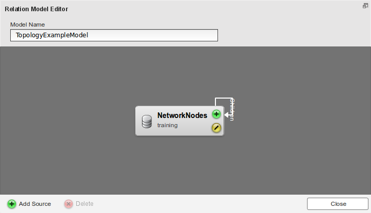 Relation Model Editor
 - To describe the data with appearance rules, click the yellow “/” button.
- In the window that appears, on the Label page, select the Name token to use it in the Label.
- Click the Color tab and click the Add button to add a Color Filter.
- In the window that appears, change the name to "Status Rule".
- Click Add Color. Change the color to red and set the Property' to Status.
- Leave the Comparator as = and in Value, enter "0".
- Click the Add Color button three more times. The Property and Comparator dropdown list selections should stay the same for each color and the Values should increment by one for each color. If this did not happen, be sure to set Property to Status, Comparator to =, and Value to "1", "2", and "3". For these items, set the colors to orange, yellow, and green (orange for "1", yellow for "2", green for "3"). Click Close.
- If the Color Filter dropdown list does not say Status Rule, click the list and select Status Rule.
- Click the Icon tab and click the Add button.
- In the window that appears, set the name to "Icon Rule" and click Add.
- Click the Available Icons button and select the icon for Server 1. Click OK.
- Click the dropdown list under Property and select Type.
- Leave Comparator as = and for Value enter "Server".
- Click Add two more times.
- For the first item, set the icon to Router and in Value, enter "Router".
- For the second item, set the icon to Monitor and in Value, enter "Workstation". Click Close.
- If the Icon Filter dropdown list does not say Icon Rule, click the list and select Icon Rule.
- Click Close to exit the Configure Appearance window and then click Close again to exit the Relation Model Editor.

Creating a Root-level Data Collection
- On the Data Collections page, switch the Collection Type to the Flat Collection mode by clicking on the toggle switch.
- Click Add create a new data collection.
- For the Data Collection Name, enter "TopologyExampleRouters" and in the Data Source dropdown list, select training.NetworkNodes.
- Check the Filter option and click Add Rule.
- In the Property dropdown list, select Type.
- Leave Comparator as = and set Value to "Router".
- Click OK.
Creating a Stack
- Navigate to the Stacks & Boards page.
- Click Add Stack, enter "TopologyExample" for the title, and click Add Stack.
Creating the Topology Widget
- Select the Builder mode, and the TopologyExample stack.
- Click the Add Widget quick action:
- The Add Widget Wizard should launch on the Data step:
- Widget Type: Diagrams -> Topology
- Widget Name: TopologyExample
- Data Collection: TopologyExampleRouters
- Click the Next button.
- On the Visualization step:
- Relationship Model: TopologyExampleModel
- Max Number of Hops: 3
- [optional] try out the other visualization options.
- Click the Next button.
- No need to do anything on the Options step, just click Finish to complete the wizard.
- The Add Widget Wizard should launch on the Data step:
- You should now have a topology diagram on the board.

Topology Widget Visualization
Viewing the Topology Widget
- Navigate to the Builder page and click on the tab for the stack called TopologyExample.
- Use the mouse to drag (click and drag) and zoom in or out (mouse wheel up or down) on the widget as needed.
- Different nodes in the diagram can be clicked to perform a drill down and see connections at different levels in the hierarchy.

The completed TopologyExample